In municipal water supply, building water supply and drainage, and water treatment plant projects, the Gate Valve is one of the most common types of isolating valves. It is primarily used within pipelines as a fully open or fully closed shut-off device, ensuring the medium can pass through unimpeded or be completely blocked.
However, in engineering design drawings, P&IDs (Piping and Instrumentation Diagrams), and construction drawings, valves are not depicted as their actual appearance. Instead, they are represented using standardized graphic symbols. This specific symbol is known as the Gate Valve Symbol.
Common forms of Gate Valve Symbol
Gate Valve Symbol
A gate valve is a full-open or full-closed isolating valve. Its fundamental symbol on P&IDs consists of two triangles pointing toward each other along a pipeline.
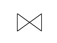
According to the different design specifications, the gate valve symbols may also vary, but the core features are basically the same.
Common symbol standards include:
ANSI / ISA Standards (commonly used in the United States):
Typically represented by two symmetrical triangle tips facing each other along a horizontal line. A handwheel or actuator symbol may sometimes appear above the valve symbol.
ISO / EN standards (international common)
Similar to ANSI, but the details are slightly adjusted, often used in engineering international projects.
Additionally, gate valve symbols may include auxiliary markings in certain engineering drawings, such as:
- With electric actuator: A motor symbol is shown above the valve.
- With pneumatic actuator: A pneumatic symbol is added above the valve.
- With position indicator: An indicator is placed beside the symbol to show valve opening status.

Role of Gate Valve Symbol in P&ID Diagram
In P&ID (Piping and Instrumentation Diagram, piping and instrumentation flow chart), the gate valve symbol not only represents the valve itself, but also relates to the function of the valve, the installation location, and the drive mode:
- Quickly identify the type of valve: distinguish the symbol from ball valves, butterfly valves, etc. to avoid selection errors.
- Clear control mode: through the symbol of additional marking to distinguish between manual, electric, automatic control.
- Convenient maintenance management: construction and maintenance personnel can judge the valve structure and function according to the symbol.
Water system application example:
In the municipal water supply network P&ID, gate valve symbols often appear in the pump room water main, the main line branch, isolation of the two ends of the maintenance section, to assume the key role of opening and closing and isolation.
In the water plant (such as sedimentation tanks, filtration tanks) process piping, gate valve symbols identify the location of valves used to control the direction of water flow, isolation equipment.
Other valve P&ID symbols

How Are End Connections Represented In The P&ID?
In P&ID, gate valve end connections (e.g., flanged, threaded, butt-welded, etc.) are not normally represented directly in the gate valve symbol itself.The core purpose of P&ID is to demonstrate process flow, equipment function, and control system logic, not detailed piping mechanical connection details. However, end connection information is clearly represented in the drawing system by the following means:
Common End Connection Forms and Representation in P&IDs
End Connection Type | P&ID Representation | Description |
Flanged Connection (Flanged) | Short lines on both ends of the valve symbol, labeled “FLG” or “FF/RF” | Most common; easy to install and remove; suitable for low to medium pressure water gate valves |
Butt Weld (BW) | Valve ends drawn as straight lines continuous with the pipe; labeled “BW” in data sheets | Suitable for high pressure or large diameter systems; rarely used in long-distance water pipelines |
Socket Weld (SW) | Short lines at both valve ends; labeled “SW” in data sheets | Common for small diameter, high-pressure systems |
Threaded (NPT/BSP) | Short lines at both ends; labeled “THD” or “NPT/BSP” | Often used in small-diameter or temporary pipelines |
Grooved (GRV) | Short lines at both ends; labeled “GRV” or “VIC” | Common in fire protection and building water supply systems; quick installation |
Wafer Type (Wafer) | Valve shown clamped between flanges; typically labeled “Wafer” in valve specs | Rare for gate valves; common for butterfly valves |
Double Flanged | Same symbol as flanged connection; labeled “Double Flanged” in data sheets | Common in municipal large-diameter gate valves |
Gate Valve P&ID Example

The symbols included in P&IDs represent various equipment in the process, such as actuators, sensors, and controllers.
Controller→ Refers to the signal processing and control logic section, such as the control module in DCS/PLC.
Actuator → Indicates a valve actuator that receives a control signal to switch a valve.
- FV-01 (Flow Valve 01) → The symbol in the red circle is a regulating valve with an actuator that receives a control signal to regulate the flow.
- Gate Valve → The two triangular symbols with opposite tips in the lower right corner indicate a manual gate valve, which is used to fully open/close to control the flow of material.
Sensor→ Temperature, pressure and other measuring instruments labeled, used to detect process parameters.
- TT→Temp Transmitter
A system has 4 temperature transmitters, then we can identify them as: TT01, TT02, TT03 and TT04.
- TC→Temp Controller
- PT→Pressure Transmitter
- FC→Flow Controller
- I/P Transmitter (I/P 02) → Converts electrical signals into pneumatic signals to drive pneumatic actuators.
For other symbols, please read Standard P&ID Symbols Legend pdf.
P&ID Conduits and Connections
The conduits or connections on the P&ID also tell us about the meter:
- Solid line: Indicates that the connection is through a conduit.
- Dotted line: Indicates that the connection is electrical.
It is valuable to familiarize yourself with these different types of connection symbols because they can help you understand the function of the meter even if you don’t know the code.
P&ID Meter Location
Now that we know that the device FV01 is represented by a circle, we can also learn the location of the meter or device from the P&ID.
- No lines in the circle: The instrument is located in the field, close to the process and the operator.
- Solid line inside the circle: The instrument is located in the control room (accessible to the operator).
- Dotted line in circle: Instrument is not directly accessible.

Conclusion and TFW Valve Solution
Through this paper we can see that Gate Valve Symbol is not just a marking on a drawing, it is the language of communication between engineering design, construction, and operation and maintenance. Being familiar with these symbols and interpreting them correctly can help engineers, designers, purchasers and operation and maintenance teams to avoid misunderstandings and improve work efficiency during the whole project life cycle.
In actual projects, the symbols behind the corresponding real equipment. For municipal water supply, building water supply and drainage, waterworks and other water system projects, choosing reliable gate valve products is crucial.
As a professional manufacturer of water system valves, TFW Valve not only provides low and medium pressure gate valves in accordance with international standards, but also offers a variety of end connection forms (flanged, butt-welded, grooved, etc.) and different actuation modes (manual, electric, pneumatic) according to project requirements. We insist on strict quality control and perfect after-sales service to ensure that each valve can operate stably and efficiently in your system.
If you are looking for high quality and standard gate valve products for your project, welcome to contact TFW Valve and let our professional products and technical support escort your project.


